Penon — bench phase
Technical documentation
Principle, variants, bench, measurements and mechanics of Penon — work in progress.
Penon is a masthead wind sensor with no moving parts. Wind is read in the way it disturbs an ultrasonic field between fixed transducers; an inertial unit corrects the measurement for the boat’s motion. The project is in its bench phase: the physics is measured before anything is frozen.
The principle
- Nothing moves. No cups, no vane, no bearing: fixed transducers and an ultrasonic field. Nothing to seize, nothing to wear.
- A reciprocal measurement. The medium cancels out, the wind remains.
- Motion corrected. A masthead moves — roll, pitch, acceleration. The on-board inertial unit corrects the measurement in real time: what reaches the helm is the wind, not the boat’s motion.
Two tracks
| Track | What is published |
|---|---|
| Time of flight | A first version, explored on 26 August 2026. |
| Resonance | A cavity formed by two discs, probes mounted flush with the lower disc, upper disc as reflector. This is the track currently on the bench. |
The bench
The project opens at the workbench, not on the water. The cavity is measured first: resonance frequency, quality factor, phase slope.
The set-up fits on a breadboard, from transmission to reception: a frequency sweep around 40 kHz, the received signal read on the oscilloscope, then an op-amp amplification stage added to the chain (18 September).
Measurements
First results on the aluminium cavity:
| Quantity | Measurement | Note |
|---|---|---|
| Resonance frequency | 39.7 kHz | 2 October |
| Quality factor Q | 287 | ten times the working assumption |
| Mechanical distance | recovered from the mode spacing | no fitted parameter |
| Off-resonance amplitude | predicted by the Lorentzian within 2 % | |
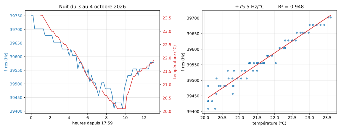
| Thermal drift | 75 Hz/°C measured, 70 Hz/°C predicted | 4 October, no fitted parameter |
The thermal drift was recorded over one night, with no mechanical intervention. The residuals fall to the bench’s noise floor: the relation is explained down to what the instrument can resolve.
Mechanics
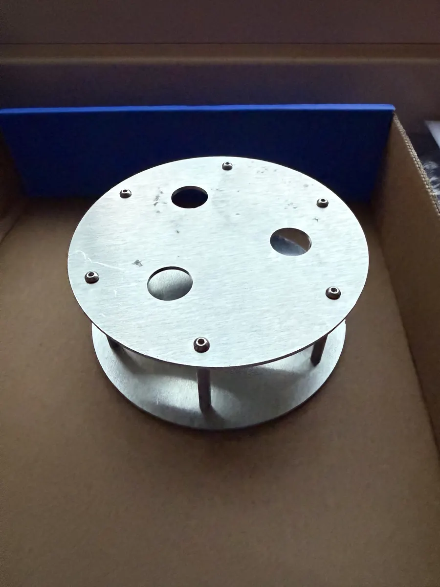
Both cavity discs are machined from aluminium, then assembled on spacers.
| Step | Date | What changes |
|---|---|---|
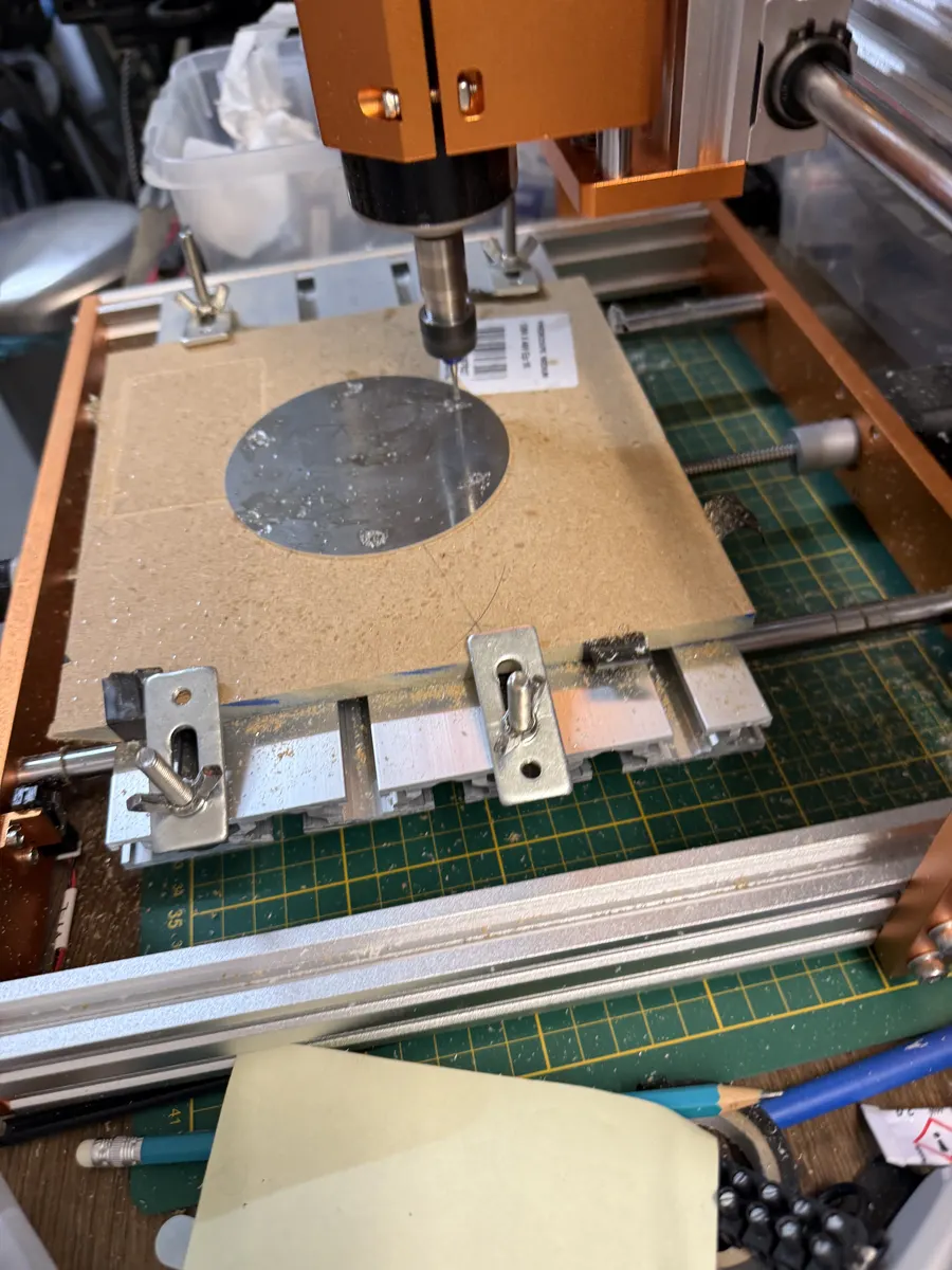
| Machined discs | 30 Sept. | Both discs milled and drilled in aluminium on a CNC mill |
| Cavity assembled | 2 Oct. | Spacers in place, screws around the rim, probe openings cleared |
Machining the discs
Drill both plates together, stacked in the fixture, for perfect alignment; do not change Z0 for the transducer openings. Once the M2.5 holes are made, screw the stack to the spoilboard as well as the double-sided tape.
3D model
Published files
The CNC programs of the V2 resonance variant are published as they are, signed with the Tadorne publication key and timestamped by FreeTSA (RFC 3161), under the CERN-OHL-S v2 licence:
- Fixture in the spoilboard — signature, timestamp
- Drilling both plates — signature, timestamp
- Milling the lower plate — signature, timestamp
- Licence text, release notice
The same files, and the source of this site, are in the repository github.com/tadorne-org/penon. Key verification: tadorne.org/verify.
The horizon: dedicated silicon
Today the measurement chain relies on parts a single supplier can discontinue. The answer is an in-house, characterised measurement core: validated first in RTL on an FPGA, then rebuilt in silicon. In the same family of silicon time measurement: OpenTDC.
Status and open points
| Point | Status |
|---|---|
| Bench (M1) | in progress: frequency and Q measured, thermal drift characterised; phase slope and method to be published |
| Housing | to be designed for machining, once off the bench |
| Electronics | transmit–receive chain on a breadboard; board and firmware documented when published |
| Calibration (M3) | reference bench and a certificate per piece, to come |
| Licences | G-code under CERN-OHL-S v2, licence stated with each later release |
What comes next is on the roadmap: nine milestones, from the bench to the first series.